
Installing Air Conditioning in '99 Miata
by Doug Thomson
Fine Print: Please note
that while the pictorials "appear" to be step-by-step, there may
be important information not explicitly stated.
Check your Mazda manual. Do all mods at your own risk! No guarantees! In fact,
if you don't know what you are doing, take your car to a garage!
When we bought our Miata we couldn't imagine why we might want air conditioning. Well, after a trip through the semi-arid interior of British Columbia, that included a long stretch of very hot travel in the pouring rain, we found our reason.
Recommendation #1. If you know a parts person who can find you a dealer installation kit for your car, buy the thing. New parts, everything there, and no missing bits and pieces all combine to make the experience simple and without many of the frustrations you will have when piecing a kit together. The down side is the cost.
The installation is not difficult, but you will need a shop manual for torque specifications, etc. A wiring diagram is also a good idea. Although all the connectors are application specific and it's hard to make a mistake, it is still nice to be able to check the wiring. The dealer installation kit comes with no instructions (only a parts diagram and quality control checklist for the dealer's records).
The 99 Miata has a Denso compressor that uses Denso 9 compressor oil. This particular viscosity (150) is somewhat difficult to find. If your Mazda dealer does not have it on hand, you should be able to find it at a Toyota dealership - many Toyota's use the same compressor. Make sure you use the correct oil for your compressor ... if you don't, it will be an expensive learning experience. Fortunately for those of you who use the dealer installation kit, Mazda ships the condenser pre-filled with the appropriate oil, and you'll only need enough to lubricate the o-rings on the piping connectors. For the purpose of lubricating the o-rings you can steal enough oil from the compressor by uncapping it and dipping in a "clean" bolt. The threads will hold enough oil for your purposes - put in a little glass jar (with a cap). This will also prove a double check to make sure the compressor does have oil in it! Make sure you recap the compressor to protect the oil ... it's hydroscopic and will absorb water from the air - not good. It will also mess up your paint, so be careful with drips. Finally, it tends to be a skin irritant, so apply with a cue-tip, or use surgical gloves, a brush, whatever.
Click
on the thumbnails to see full sized image - they often have extra words, arrows,
etc. as well.
The link opens a new window. Close it to return here.
Click Picture for Parts
List/Diagram
|
Disconnect
the negative battery terminal!!!!! Interior of Car: Switch DON'T DO THIS! Instead just use
a small screw driver to gently pry out the dummy button. It comes
out very easily. You'll find the connector for the A/C nicely attached
to the back of the dummy button. Total time for the installation of
the A/C switch should be about 15 seconds.
|
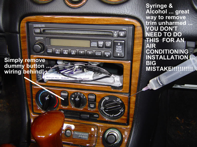 Image 1 |
|
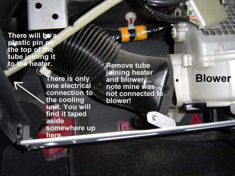
Cooling Unit / Evaporator Unit The cooling unit mounts between the blower and the heater. Right now you have a piece of plastic tubing joining the blower and heater. To get at this area, first remove the glove box. If you look at Image 2 you will see that when I removed the glove box I found that my blower was not attached to the tube. Remove the tube ... it should be attached by a plastic pin at each end. The one on the heater side is on the top of the tube. Image 3 shows the glove
box brace. It is attached on the left and right by two screws and
on the far right by a cadmium plated bolt. |
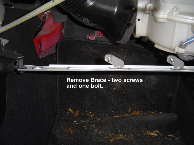 Image 3 |
|
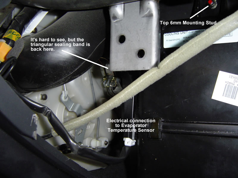
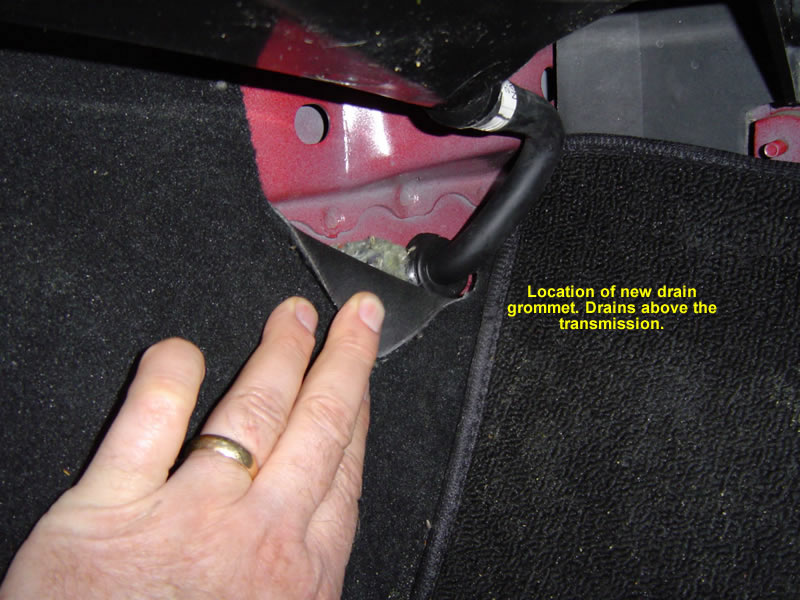
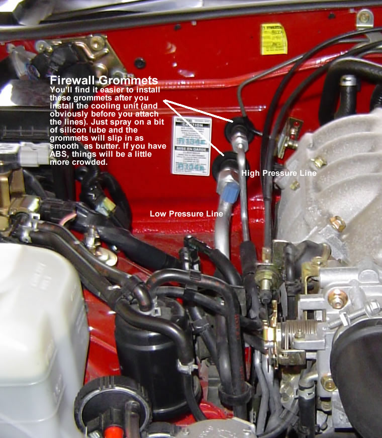
Cooling Unit / Evaporator 2 Before installing the cooler unit, there are three grommets you will need to remove. One is for the cooler unit drain (for draining condensation) See Image 5. Replace it with the new grommet - it has a hole for the drain tube. You will also need to install the drain tube to the cooling unit unless you want your passenger to have wet feet. The other two grommets are in the firewall where the high and low pressure connections to the cooling unit enter the engine compartment (See Image 6). Don't install them until after you have the cooling unit installed. Then, lightly spray with silicon lube (rubber friendly) and the grommets will slip on very easily (just put them on before you attach the lines (duh!). The cooling unit is attached to the heater by a triangular, one piece sealing band/plate, and to the blower unit by a rectangular, two piece sealing band/plate. Find the correct orientation and put the triangular band loosely on the cooling unit before putting it in place. Move the unit into place and position over the existing 6mm studs ... the unit will align with the proper studs as you move it into place. Fasten the top stud first and then loosely fasten the unit into place. Adjust the triangular sealing band and fasten the clamp. Attach and tighten the two piece rectangular sealing band joining the cooling unit to the blower, and finish tightening the nuts on the 6mm studs. The only electrical attachment to the cooling unit is for the Evaporator Temperature Sensor (see Image 4). You should find the connector taped to other wires to the above and to the driver's side of the glove box opening. It won't be hidden and it is the only connection that will attach to the cooling unit. Make sure everything is still aligned and reinstall the glove box. You are finished in the cabin. Note from Jon Arden On my '99, the fastener
for the triangular band is located on the top of the band - not on
the side of the band like pictured on the author's car. On my band,
the fastener is not accessible by human hands once the evaporator
is in place. Article should mention that the bands do not fit very
tight and can be easily slid back and forth even after fastening.
I had to fasten the triangular band BEFORE installing the evaporator. |
|
|
Engine Compartment - Removing Stuff Jack up the car and put it on jack stands. A ramp will also work, but jack stands give you more room and better lighting. Remove the belly pan. Do this BEFORE you start trying to route the high & low pressure lines. There are two hidden nuts on the front of the belly pan. Find the one on the passenger side first ... big opening, then you will easily find the driver's side nut. A universal joint on your socket, and a long extension is necessary. (Tip ... if your universal joint is floppy, wrap the joint with electrical tape to stiffen it.) Come back up top and remove
the cooling fan ... just two bolts at the top. Don't worry about removing
the electrical connection ... you'll be able to set it aside without
fussing with the connection. Remove the two mounting brackets that hold
the rad in place. You don't need to remove the rad, don't worry, you
just need to push it back to install the condenser. Remove the air tube
(to air filter). Loosen the Power Steering drive belt and remove the
belt. You will need the proper replacement belt for PS & Air) -
comes in the kit. |
|
|
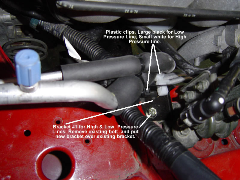
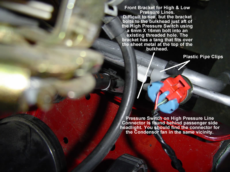
Engine Compartment - Adding Bits & Pieces Okay, now is the time to start putting on some little bits and pieces. We'll start on the driver's side behind the headlight (see Image 7) where we will attach the new relays. There are two and they are identical. One serves the A/C circuit, the other the condenser fan. Bolt the relays onto the bracket using 6mm X 16 mm bolts and nuts. Attach the electrical connections that are stored to the right on the same bracket (see Image 7). Plug each connector into the correct relay (just keep them in the same orientation). It doesn't really matter, but it will keep your wiring neat. Now go to the passenger side and attach the brackets for the aluminium high and low pressure pipes. The one closest to the firewall is a simple L bracket with a large and small square hole punched into the "L". The other one is mounted just aft of the pressure switch on the high pressure line. You will find a tang on the bracket that fits over the sheet metal and aligns the bolt hole with an existing 6mm threaded hole on the vertical sheet metal of the fender bulkhead. You will have to explore to find the right hole. The pipes will attach to these brackets with plastic clips that snap into the square holes (see Images 8& 9). You can now install the high & low pressure lines that attach to the cooling unit. Start with the low pressure line. Slip the plastic connectors over the tube and route the line past the brackets - slip up from under the vacuum lines - you shouldn't have to remove any vacuum fittings. Remove the cap and lubricate the o-ring with compressor oil. Torque ALL pipe and hose fittings using two wrenches, one to hold the pipe from twisting, and one to turn the nut. Remember that these fittings are aluminium and the torque specs are in inch pounds, not foot pounds. If you over-tighten you can damage an O-ring, strip threads, or stretch fasteners, none of which is good. Close the pipe clips and fasten them to the brackets. Find the pressure switch
connector (Image 9), behind the passenger headlight, route the wire
and attach to the pressure switch on the high pressure line. You should
find the connector for the condenser fan in the same location. |
|
|
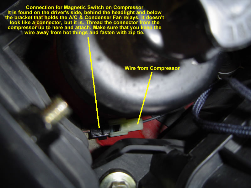
Engine Compartment - Getting Down Now, pick up the cast iron compressor bracket and get down under that Miata. The bracket is attached to the engine block by 5 bolts (4 - 10mm X 25mm and 1 - 8mm X 75mm). There is an existing bolt in the block where the 8mm X 75mm bolt attaches. You will have to remove it before installing the bracket - you will not use that bolt again (see Image 10). Important Point: If your block is like mine, the threads in the bracket mounting holes will be rusty. I advise that you get the correct thread taps and clean out those holes so that you can get proper torque on the bolts. Use the 75mm bolt to align the bracket and attach the bracket to the block with all five bolts. Torque the 4 - 10mm bolts first and follow with the longer 8mm bolt. The 10mm bolts are recessed into the bracket and you will need a thin walled socket to torque them. You can now install the compressor to the bracket and torque the four mounting bolts. Make sure you have the fitting holes capped so you don't spill any of the oil from the compressor. You also need to protect the compressor oil from contamination (water from the air - remember the hydroscopic thing - and any little bits of dirt!). Now connect the wire from the compressor (for the magnetic switch) to the connector that is found behind the driver's side headlight and almost under the bracket that holds the new relays you installed (see Image 11). This one is not easy to find and it doesn't really look like a connector ... it is! I had to trace the wiring back to find it, so a thank-you will be appreciated! |
|
|
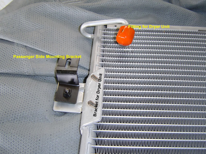
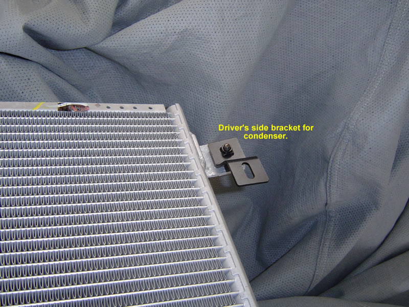
Back up top Mount the brackets to the condenser as shown in Images 12 & 13. Now is the time to test fit the dryer unit to the condenser. You can gently bend the pipe at the top passenger side of the condenser to mate it with the condenser threads when the dryer is attached to the bracket. Make sure you have it properly oriented. Upside down won't work! You cannot get the condenser in place with the dryer attached, so don't bother trying ... well, unless you want to remove the rad.. Note from Jon Arden The condenser is easily
installed with the dryer attached; you simply install the assembly
from the bottom of the car. There is plenty of room to spare for doing
this. Attempting to remove or install the dryer with the condenser
already installed on the car (as suggested in the article) is nearly
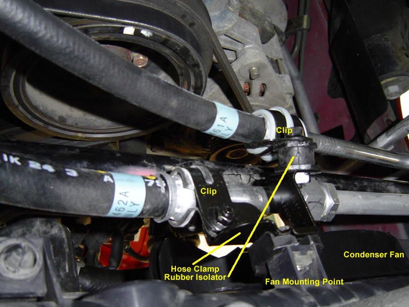
impossible, and is totally unneccessary. Push the radiator back toward the engine (making sure the cooling fan is out of the way). Slide the condenser in front of the radiator. Align the two pins on the bottom of the condenser with the holes in the mounting frame. Bolt the condenser into place (this should remove some skin from your knuckles). Reattach the radiator but do not attach the cooling fan ... you still need to put on the new drive belt and it will be easier without the fan. Now for the condenser fan. There are two mounting holes at the top of the radiator and two at the bottom. There is a short bracket that attaches the outboard (passenger side) bracket to the rad - install it on the fan now. (See Image 18). Back under the Miata, start two 6mm X 16mm bolts into the holes. Slide the knotches in the bottom of the fan onto the bolts and tighten the top bolts. Tighten the outboard bottom bolt. The inboard bottom mounting bolt also holds a special bracket for the rubber A/C hoses. See Image 14 for the orientation and mounting of this bracket. Note that when you mount the hoses (a little later), make sure clips attach to the hoses at the metal unions on the hoses. Do not attach the clips to the rubber part of the hose. Finally, find the connector for the condenser fan behind the passenger side headlight and connect your fan to power. |
|
|
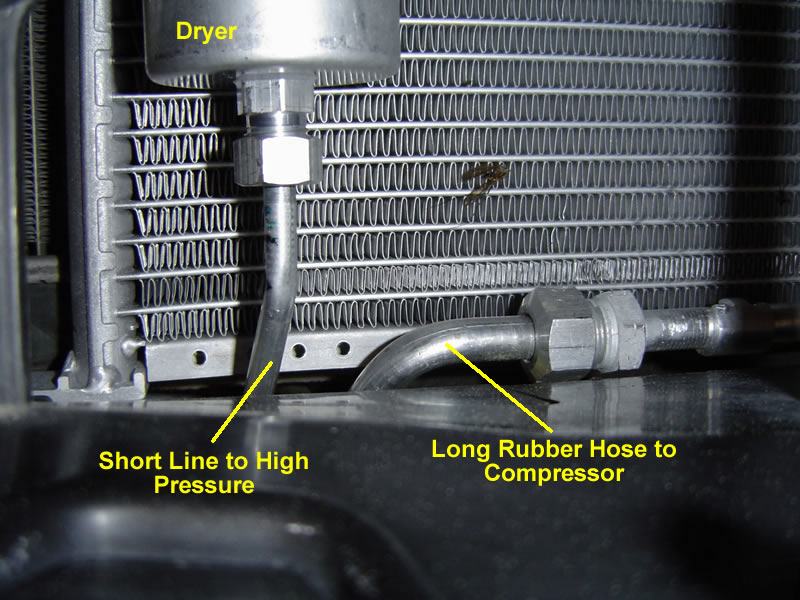
The Hard Bits Attaching many of the remaining parts is made difficult by cramped conditions and the need to get rather large jawed wrenches into tight places. Start with the dryer. It is the canister that attaches to the front passenger side of the condenser (see Image 12). Again, make sure you lubricate the o-rings on all these fittings and do not over torque. Slide the dryer into position and lightly fasten with two 6mm nuts. Now snug up the fitting to the condenser, tighten the bracket nuts, and torque the pipe fitting. Lube the o-rings and lightly attach the short bent aluminum tube that attaches the bottom of the dryer to the high pressure line attached to the cooling unit. See Images 15 & 16. When everything is aligned, tighten the fittings. |
|
|
The Rubber Hoses Torque ... if you don't have an Inch Pound Torque wrench, now is the time to beg, borrow, or buy one. The rubber hoses attach to the compressor and it is important that you acutally torque these bolts to specifications. The attachments are offset and insufficient torque will result in leaks, too much torque risks seriously damaging your compressor. So, get an Inch Pound Torque Wrench. The long hose attaches to the fitting at the front of the condenser (see Image 15). The bent aluminium section snakes under the compressor, is supported by the bracket on the inboard side of the condenser fan (see Image 14), and attaches to the top of the compressor (see Image 17). Lubricate the o-ring and loosely attach the hose to the fitting on the front of the condenser. Loosely attach to the clamp (Image 14), and position the end at the top of the compressor. From the top, using a long extension, remove the shipping cap from the top of the compressor, lubricate the o-ring on the hose fitting, and lightly snug the fitting to the compressor making sure you do not damage the o-ring. Now torque the fitting to shop specifications. Return to the front of the condenser and tighten the fitting there. Finally, secure the hose clamp under the fan, ensuring that the clip is attached to the metal union in the hose. Use
the same strategy to attach the short rubber hose to the low pressure
pipe from the cooling unit and to the attachment point on the side
of the compressor. To recap, it attaches at the low pressure pipe,
is secured by the clamp (Image 14), and at the compressor. Again,
make sure you align all the fittings, lubricate the o-rings, and apply
the proper torque at the compressor. |
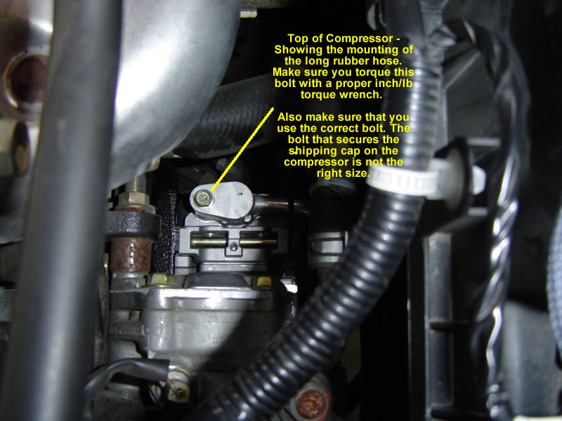 Image 17 |
|
Image
18
Showing condenser fan installed. |
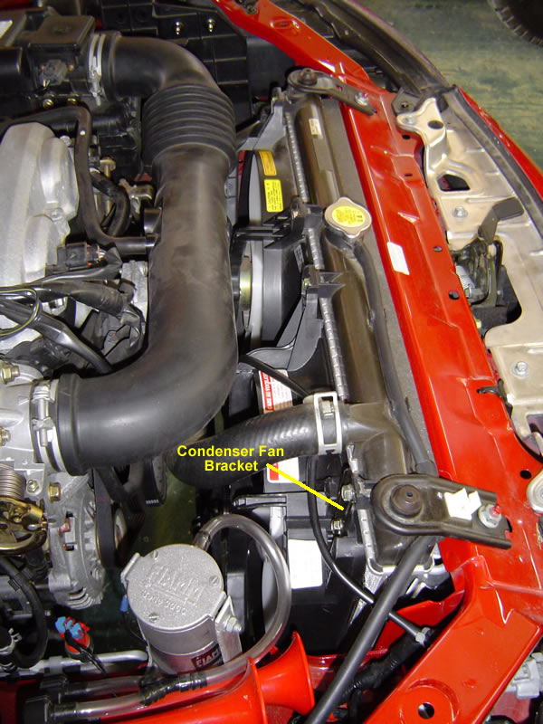 Image 18 |
|
Last Bits
|
|
|
Check List
|


Addendum from Louis Descoteaux, Quebec, Canada
In the summer of 2006, I went to Virginia in my miata with my girlfriend and during this trip, I really understood why I made a mistake by buying a car, even a convertible, without AC. If you made the same mistake, read on...
I had trouble to find an AC kit for a 99 miata. The problem is that Mazda discontinued the kit (at least in Canada). The kit was sold at 1060$ CDN at my city dealership. They still had the parts list and the price, but no more kit. Going through hoops, I got in touch with Paul at Mazmart (Atlanta, GA) who put together an AC kit for me with a mix of new and used parts. Mazmart phone number is (800) 221-5156, just ask for Paul. You can ask him to send you the parts list before ordering, so you can check that you got everything (compare that list with the list from Doug, and don't worry about the little adapters/hose holders, they'll be attatched with the main parts). Paul did forget to add the proper driving belt, and added it to the kit at no charge for me upon asking. Be sure to get a new dryer, new o-rings and a new belt, the rest can be either new or used (mine were used, to save money). I got the kit for 700$ US + 110 $ for shipping (to Canada, people from the US will save even more money).
Only two parts were missing from my kit, they are the two bands to link the evaporator (under the glove box) to the fan on the right side, and the heater matrix on the left side, but I bought a roll of aluminum duct tape (the one with unremoveable gunk instead of glue on it) and it did very well.
I would not rate this modification too difficult, but be prepared to spend several hours under your car and buy a M10x1.25 tap to clear the holes in the engine block to secure the compressor, they WILL be full of rust. A M6x1.25 tap is also a good thing to have, since those holes will be also rusty (the two bolts holding the condenser (front radiator), and some others holding supports for hoses)
Get a torque wrench for those two bolts holding the two hoses that connect to the compressor. Torque is: 87 to 138 inches-pounds. Watch here for the word inches. Not foot. So if your torque wrench is in foot-pounds, divide by 12 giving 7.25 to 11.5 foot-pounds. If you have a standard I-torque-my-wheels-with torque wrench and the torque scale on it starts at 20 foot-pounds, then you got a trip to your local Canadian Tire (or any other variant) to get a smaller one. For the other hoses connections, I did every torque without any torque wrench, considering this is all aluminum fittings, you torque them to a snug fit, nothing more. Your AC technician will see leaks if you did not torque enough and tighten them, but if you overtorque, you'll have to talk to Paul again... And he'll want more money... ;)
Finally I would recommend
that when you completely assemble the kit, to drain the compressor oil and
bring it to a competent air conditioning technician, who will know how much
oil to put in the system, and which type. If I have only one advice to give
people who attempt this: go to a reputable AC garage when you're finished,
they will do a good check of your work. More, if you can, go see your AC tech
before adding the AC kit on your car, and ask them if they got special tips
for you (oil the o-rings, bring me the compressor empty of oil, etc...)
| Back to the Garage |
27 January, 2008 |
| [Home] - [FAQ] - [Search] - [Sponsors] - [Forums] |
| [Garage] - [Clubs] - [Contact Us] - [Disclosures] - [More...] |
Copyright
©1994-2024, Eunos Communications LLC
|