Cooling System Troubleshooting
Revision D – 02/07/2009
The Miata cooling system is
described on pages E-2 through E-14 of the 1990 Miata Factory Workshop Manual,
and much of the material below, including illustrations, is taken from that
manual. Model years beyond 1993 have a number of differences, but the basic
troubleshooting procedures should be similar. Hopefully this article will be
useful to many of those having cooling issues. However, there is really no
substitute for the FWM if detailed information is needed.
A knowledge of what
conditions should exist in the cooling system is invaluable in troubleshooting.
So for the benefit of those who do not have a complete set of manuals for their
car, this article starts with a somewhat comprehensive set of desired cooling
system parameters.
Basics
Coolant Capacity and
Mixture
The cooling system capacity
is 6.3 U.S. quarts. Mazda’s recommended anti-freeze solutions for the Miata are
as follows:
|
Minimum Temperature
|
Volume Percentage (%)
|
Specific Gravity @ 68°F
|
|
Water
|
Glycol
|
|
-16°C (3°F)
|
65
|
35
|
1.054
|
|
-26°C (-15°F)
|
55
|
45
|
1.066
|
|
-40°C (-40°F)
|
45
|
55
|
1.078
|
Table 1. Coolant Mixture Recommendations (Mazda)
Remember that the primary
task of liquid cooling is to transfer heat energy from the metal parts of the engine
to the radiator and then to the air. Water has a specific heat of 1.00, but the
specific heat of glycol is only 0.571, meaning that a given quantity of glycol
will carry away only about 57% of the heat that the same volume of water will
transfer.
A more complete table of
freezing points vs. % ethylene glycol is given in the Handbook of Chemistry and
Physics:
|
Freezing
Temperature
|
Volume Percentage (%)
|
Specific Gravity
@ 60°F
|
|
Water
|
Glycol
|
|
-3.9°C (25°F)
|
87.5
|
12.5
|
1.019
|
|
-6.7°C (20°F)
|
83
|
17
|
1.026
|
|
-12.2°C (10°F)
|
75
|
25
|
1.038
|
|
-17.8°C (0°F)
|
67.5
|
32.5
|
1.048
|
|
-23.3°C (-10°F)
|
61.5
|
38.5
|
1.056
|
|
-28.9°C (-20°F)
|
56
|
44
|
1.063
|
|
-34.4°C (-30°F)
|
51
|
49
|
1.069
|
|
-40°C (-40°F)
|
47.5
|
52.5
|
1.073
|
Table II. Freezing Point vs. % Ethylene Glycol
The boiling point of water at
14.7 psia is 212°F, and if the pressure is increased, it rises. The pressure in
the Miata cooling system should be between 11 and 15 psi (25.7 to 29.7 psia)
maximum, which would place the boiling point of a 50/50 coolant mixture at
around 265°F (at 15 psi) according to the Prestone labels.
Unfortunately I could not
find information correlating the “H” reading on the Miata temperature gauge
with coolant temperature. The 1990 FWM is written as though the Water
Thermosensor is the temperature gauge sensor, which it is not. There is no data on the actual gauge sensor, although the
manual spec on the gauge itself states that the gauge should point to “H” for a
resistance to chassis ground of 20 ohms (18 ohms for Canadian cars).
Coolant Flow
The coolant flow is shown in
Figure 1. The arrows clearly show the flow, but the diameters of the heater
hoses are actually considerably smaller than those for the radiator hoses, as
you can tell from looking at your engine bay. If the thermostat is removed,
flow will be unbalanced, since the water pump and the thermostat housing are
both at the front of the head. As a result, the rear cylinders will run hotter
than the front. The lesson here is to keep the thermostat installed; if you
have cooling problems, removing the thermostat is not a good long-term
solution.
Note that the diagram shows
an “IG” relay. That is actually the Cooling Fan Relay, as you can see on the
cover of the Main Relay and Fuse Box.
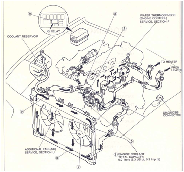
Figure 1. Coolant Flow
Note that there is no coolant
shutoff valve at the heater hose connections. Coolant always flows through the
heater core regardless of the position of the heater controls in the passenger
compartment. It is very important
that the heater core path from the rear of the head to the water pump inlet not
be blocked, since otherwise hot coolant in the rear of the cylinder head will
stagnate, making the rear of the head overheat.
Note the small hose at the
bottom of the thermostat housing that carries coolant output from the cylinder
head through the input side of the thermostat housing and down to the water
pump input. This assures that hot coolant from the head flows through the
thermostat housing when the thermostat is closed, exposing the thermostat valve
to the coolant. If this path is blocked by metal shavings in the thermostat
housing outlet nipple, or anywhere in the small hose, the coolant will not flow through, and the thermostat will not
open early enough. A symptom of a blocked path here would be temperature rising
above normal on first warm-up, then suddenly dropping to normal sometime later.
This connection can be seen in the lower right portion of Figure 2.
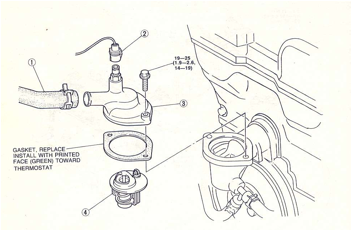
Figure 2. Thermostat Housing
Some coolant flows from the
cylinder head into the Idle Speed Control valve below the throttle body (called
the Idle Air Control valve on the 1.8L engine), then out of the ISC valve and
through the Air Valve mounted on the engine side of the intake manifold,
returning to a “tee” into the down tube from the thermostat to the water pump
input. (1.8L engines do not have an Air Valve.) The Air Valve on the 1.6L
engine is open when the coolant is cold, raising the idle speed, and closes
gradually as the coolant warms up to normal operating temperature.
Thermostat and Water
Thermoswitch
The OEM thermostat opens in
two stages. There is a “sub-valve” that opens at 182 – 188°F, and a main
valve that opens at 188 – 193°F. As shown in Figure 2, the main valve is
oriented to the front of the thermostat housing. On the cover of the thermostat
housing is mounted a “Water Thermoswitch.” This switch is open when coolant
temperature is below approximately 207°F and closed when the temperature is
higher. The closed switch activates the Radiator Cooling fan. If A/C is
installed, but not turned on, the A/C Condenser Fan (on the right side of the
radiator looking forward) will not
activate when the switch is closed.
Fan(s) and Fan Relay
The base Miata has one fan,
mounted on the left (looking forward) side of the radiator, called the
“Radiator Cooling Fan.” The Radiator Cooling Fan motor should use 5.3 –
6.5 Amps. If A/C is installed, there is a second fan on the right side of the
radiator called by Mazda the “A/C Condenser Fan.” The A/C fan motor is smaller
and the fan shroud fits on differently spaced mounting points, so the two fans
are not interchangeable.
As seen in Figure 3, when the
Water Thermoswitch is closed, the Cooling Fan Relay contacts close and power
the Radiator Cooling Fan. The connection to the Diagnosis Connector goes to its
“TFA” terminal. If the “TFA” terminal is jumpered to the “GND” terminal, the
effect is the same as closing the Water Thermoswitch, i.e. the fan should
activate if the ignition switch is on. This is a good test to determine that
the relay and fan motor are working. (This test will not activate the A/C Condenser Fan.)
If the test above fails to
activate the Radiator Cooling fan, then the 30 amp Cooling Fan fuse in the Main
Relay and Fuse Box is blown, or the Cooling Fan Relay or Main Relay has failed
open, or the fan motor is bad.
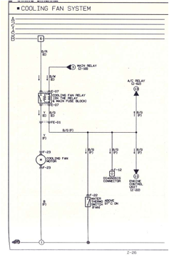
Figure 3. Cooling Fan Wiring Diagram
A/C Condenser Fan Circuit
The A/C Condenser Fan is
activated by the A/C on/off switch, on the heater/air conditioning control
panel. When the A/C switch is on, both the A/C Condenser Fan and the Radiator
Cooling Fan are activated by the ECU, through the A/C relay. Figure 4 shows the
wiring for this circuit.
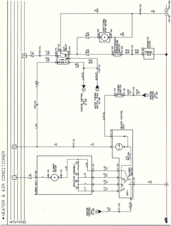
Figure 4. Air Conditioning Condenser Fan Circuit
Radiator Cap
The OEM cap’s positive
pressure valve should hold closed until at least 11 psi and not more than 15 psi
pressure. The negative pressure valve should be easily opened with two fingers
and should seal closed when released.
Coolant Reservoir
This tank connects to the
radiator at the cap, just above the positive pressure valve. The tank is not
under radiator pressure. It should be sufficiently full to allow coolant to be
sucked back into the radiator as it cools off. If air is sucked in instead of
coolant, it will expand in the cooling system as the engine warms up, and will
result in air and coolant being expelled back into the reservoir if the
pressure is over 15 psi.
The small tube from the
reservoir input to the bottom of the tank sometimes gets clogged with rust or
other deposits from the cooling system. It should be cleaned for good operation
of the system.
The other tube from the
reservoir is an overflow to vent excess air and coolant. If the hoses are
removed from the reservoir cap, be sure to reassemble with the cap’s yellow tab
pointing toward the rear of the engine; the long tube connects to the radiator
hose.
Bleeding Air From the
System
Elevate the car on ramps or jack stands; this
will ensure that the cooling system radiator cap is above the thermostat
hosing. Drain the cooling system into at least a 3 gallon bucket and
flush the cooling system before installing any new components if possible.
Flushing the system will ensure that most of the contaminants are removed from
the cooling system. Most drain plugs are in the center of the radiator;
some may not line up with the drain plug opening in the plastic under-shield.
In that case, the shield has to be removed before draining.
Fill the radiator with the coolant mix until the
level is about 1/2 to 3/4 inch above the core and then start the
engine. Keep a bucket under the center of the car just in front of the air
dam under the front of the car. Run the engine, keeping this fluid level by
topping off occasionally. The engine will come up to operating temperature, and
the Radiator Cooling fan will kick on.
The system will overflow 2 to 3 times. Each
overflow should occur as the radiator cooling fans kick on so make sure you
have a bucket under the car. Cycle the system until it does not overflow
again. After each surge and overflow, refill the radiator with the engine
still running.
Turn the engine off and let it cool for about 1/2
hour. Then fill the radiator almost up to the water neck. Squeeze the
upper radiator hose to bleed out the excess air, and then top it off
again.
Install the radiator cap and run the engine until
the fans kick on again, then check for leaks.
Troubleshooting
Leakage
The OEM radiator is aluminum
with plastic end caps. With age, the black plastic will turn a brownish-green
color and develop the appearance of hairline cracks. At this time leakage may
begin to occur at the plastic/aluminum interface. Replacement of the radiator
is recommended if this happens.
The water pump may also begin
to leak, as evidenced by coolant on the lower front of the oil pan and/or
engine block. Again this usually means the pump is due for replacement,
although the pump gasket might be the culprit.
Any of the hoses shown in
Figure 1 can deteriorate and begin leaking. If a heater hose splits, be very
careful removing it from the heater interface tube, which is thin copper and
will deform easily. If the hose has to be replaced anyway, it’s best to slit
the end of the hose along its length where it slides over the tube, instead of
trying to pull it off or pry it off. If the tube is deformed it may be prone to
leaking after hose replacement.
There is a rubber cap over
the end of an unused coolant tap at the rear of the engine block shown as
“cursed water plug” in Figure 5 (Thanks for the picture, Harry Sue.)
This cap has been known to
leak and is difficult to trace, since it cannot be seen from the top or bottom
of the engine. To get at it with the engine in the bay, I think the CAS cover
has to be removed. However, I have never had to do this and I may be wrong
about that.
A hose leak at the rear
coolant housing generally requires the coil assembly to be removed before
trying to release the hose clamp.
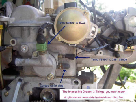
Figure 5. Coolant Cap at Rear of Engine [Rev. D]
Overheating
Mazda states in the 1990 FWM
the following causes and remedies for overheating:
|
Possible Cause
|
Remedy
|
|
Coolant level insufficient
Coolant leakage
Radiator fins clogged
Radiator cap malfunction
Cooling fan malfunction
Thermostat malfunction
Water passage clogged
Water pump malfunction
|
Add
Repair
Clean
Replace
Replace
Replace
Clean
Replace
|
Maybe we can be more
specific…
Overheating at Idle
At idle, if the temperature
gauge indicates above normal, the Radiator Cooling Fan should be running. If
not, test with the “TFA” to “GND” jumper in the Diagnostic Connector and see
whether the fan turns on when the ignition is on. If it does, the Water
Thermoswitch needs to be replaced, its connector needs to be cleaned, or its
wiring needs repair. If not, and there are no other problems with the engine
that are electrical in nature, either the Cooling Fan Relay (the “IG” relay in
Figure 1) or the fan motor is bad. Of course there is always the possibility of
an unplugged connector somewhere, or a broken wire. In a few cases the fan
blades had come loose from the motor shaft and were not turning, although the
motor was OK.
If the fan is running but the
engine still is overheating at idle, feel the top radiator hose. It should be
HOT! If not, the thermostat may be stuck closed. If it is hot, feel the bottom
radiator hose. It should be warm, but perhaps 20°F cooler than the top hose. If
it is cool, there is blockage in the radiator, or possibly in the lower
radiator hoses, preventing flow into the water pump. Sometimes old bottom hoses
collapse under a vacuum created in them by the water pump straining to pull in
water at its input.
Finally, check to make sure
there is no blockage in the heater hoses, which would stagnate the water at the
rear of the head where the temp gauge sensor is located, and cause the
temperature there to be much higher than at the front of the engine.
Overheating at Speed
This problem, assuming there
is adequate uncontaminated coolant in the system, is either poor water flow
through the Figure 1 path, or poor airflow through the radiator.
Poor water flow can be caused
by a stuck thermostat (only partially open), collapsed hose, clogged radiator,
or a bad water pump.
Poor airflow through the
radiator can be caused by air blockage due to a license plate configuration,
bugs etc. stuck in the fins, bent fins due to mishandling, and in rare cases,
the Radiator Cooling Fan running backwards!
If all of the above items
have been checked and the engine still overheats, the cooling system should be
flushed to remove any scaling or corrosion inside the water passages.
Draining and refilling of the
coolant with a lower percentage of glycol in the mixture (see Tables I and II)
would help if the glycol percentage is too high (over 50%).
Also keep in mind that
temperature sensors and gauges do go bad occasionally. If the gauge says the
engine is too hot, but there are no other apparent symptoms like
lower-than-normal oil pressure, steam or bubbles escaping into the coolant
reservoir, or a very hot under hood temperature, maybe the gauge is giving a
false reading.
Figure 6 is a page from the
FWM showing radiator removal, and Figure 7 shows water pump removal. Figure 8
is a simplified block diagram of the electric cooling fan system.
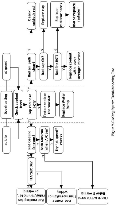
Figure 9 is a troubleshooting
tree for reference.
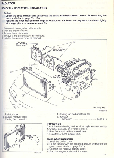
Figure 6. Radiator Removal
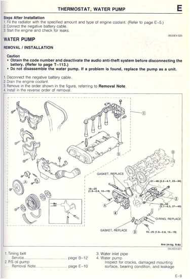
Figure 7. Water Pump Removal
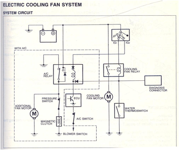
Figure 8. Simplified Block Diagram – Cooling Fan
Wiring