|
2002 Miata LS |
|
Brian Sanborn, Groton, MA |
NB Oil Sender Upgrade
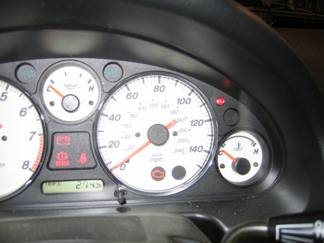
One of the first things you notice on your second generation Miata is
that the oil pressure and water temp gauges look like real sport car analog
gauges... but they are not. The first clue is that there are no
numbers on the tic marks. The oil pressure gauge (OPG) is a complete fake.
It is driven by an oil pressure sender on the side of the engine that
is a simple on-off switch. "OFF" at 0-7 PSI and "ON"
with any oil pressure above 7 PSI. It only poorly simulates an idiot
light by reading zero with no oil pressure and somewhere near "medium"
or straight up for any oil pressure above 7 PSI. But, this
is even worse than an idiot light, because there is no warning at all
if there is a sudden oil pressure failure. The gauge is also useless
for getting information about the varying oil pressures under different
engine conditions and over time as the engine ages.
The ideal situation would be a fully functional OPG and a red LED idiot light in the dash to quickly warn the driver of a sudden oil pressure loss. The first goal is very difficult to fully achieve because of the way the factory gauge is designed. The are various stages of modifications we can make to the gauge to make more linear and to eliminate the strong dampening effect on needle movement. For further information go to the OPG Mod pages on this website.
The first basic step in fixing this shortcoming in your Miata is to replace the dumb factory oil pressure sending unit with a unit that provides variable resistance based the oil pressure in the engine. Changing the sender will give you and immediate improvement by sending the factory gauge more information beyond binary ON and OFF. This will make the gauge move somewhat in response to the engine oil pressure but still does not provide a visible warning indicator for total oil pressure loss. A red oil pressure LED in the instrument cluster is the second step to get to a workable solution. Some owners have also talked about using a buzzer along with the LED. These sender change and LED mods have been covered in webpages of other Miata.net forum members. I will not try to replace their good work, but instead link to their webpages and comment on the changes I made using their instructions.
Oil Pressure Sender Replacement
The first cure is a new replacement sender from VDO that provides a 10-180 ohm signal from 0-80 PSI. The sender I choose also provides a feed to a LED in the dash. The Sheldon Stokes website has very nicely covered the install of the new sender, but I would recommend the different sender. Based on the information from Miata Forum member DAZ, I used a different sender than Sheldon Stokes but the procedure is the same. The one I used is the VDO unit that reports 0-80 PSI with a resistance of 10-180 ohms, with an additional terminal post for the 7 PSI warning switch. This unit is available from Egauges.com and is VDO part number 360-009. There is an 1/8-27 NPT to 1/8-28 BSP converter (BPTNPT) needed to match the threads on the Miata engine with the threads on the VDO gauge.
I made up a PDF file with all of Sheldon's webpage text content and his larger pictures put in context that can be used as a workbench reference. Print it out if you find it useful.
Oil Pressure LED Warning Light
The LED warning light modification should done at the same time as changing the sender. Miata Forum member DAZ has covered this very well on his CarDomain website on pages 11 and 12. He even has a detailed parts and tools list. The only major thing I would add to his coverage is the subject of getting the 7 PSI signal through the firewall and up behind the instrument cluster. I used the advice of a fellow Miata owner here in MA to run a multi-wire harness through a large grommet on the drivers side of the firewall. This allows you to cleanly bring the LED warning wire into the car behind the dash for this mod, and also allows for an easy access harness with open pins for future wiring modifications. I used a formal auto industry-like 9-pin connector from a local electronics shop on the engine bay side. These male and female connector sets are available in as small as 1 wire and on up to as much as 12 wire. I'm sure even higher wire counts parts are available somewhere. I use a 9-wire, but that may be overkill. Another important tip is that you must be very careful when you drill the hole in the face of the instrument cluster for the LED socket. Be sure to allow enough room for all of the LED socket and the wiring. There is only a small amount of space and you are drilling a little bit blind.
I made up a PDF file with all of DAZ's webpage text content and his larger pictures put in context that can be used as a workbench reference. Print it out if you find it useful.
Here are some pictures of the harness install:
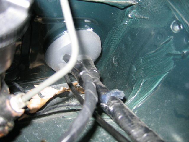
9-Wire Harness Going Through Firewall
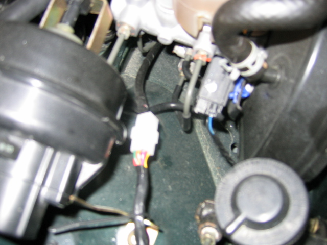
9-Wire harness connector next to cruise control unit with LED warning
harness plugged in.
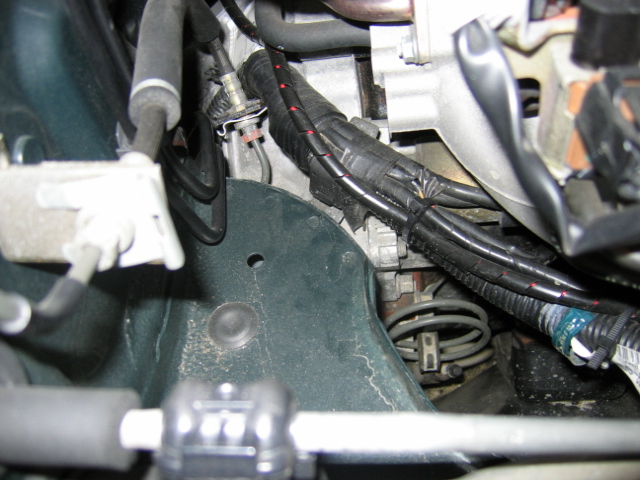
Warning LED wire coming around back of engine
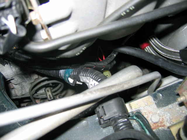
Warning LED wire dropping down to connect to warning terminal of sender
Oil Pressure Gauge Modifications Page