Miata Technical
Service Bulletin
|
| Category |
Applicable Model(s) |
Subject |
| Recall Campaign No. |
41106 |
| Issued |
14/6/91 |
| Revised |
|
|
| Recall |
MX-5 Miata with ABS
VIN JMlNA351 * NO225241 - JMlNA351 * NO233341 |
Anti-Lock Braking Recall |
Description
 "Dear Mazda Owner:

This notice is sent to you in accordance with the requirements of
the National Traffic and Motor Vehicle Safety Act.

Mazda Motor corporation has determined that a defect which
relates to motor vehicle safety exists on some 1991 MX-5 Miata
models equipped with the optional ABS (Anti-lock Brake System).

Mazda was informed by its supplier that during a certain period
of production a return passage for the front brake fluid may have
been incorrectly drilled. When the brake is applied under the
specific condition which operates the anti-lock system, such as
icy road conditions, the brake fluid in the secondary chamber of
the master cylinder could return to the primary chamber of the
master cylinder. This may result in poor braking performance.
Normal brake application (ABS not activated) does not affect
brake performance in any way.

We have made arrangements for you to have the ABS hydraulic unit
on your vehicle inspected and replaced, if necessary, free of
charge at any authorized Mazda dealer on or after June 14, 1991.

In order to minimize your inconvenience, we recommend that you
make an appointment with your dealer for the inspection and/or
replacement of the ABS hydraulic unit on your vehicle. We
estimate the actual repair will take approximately one hour.
Scheduling time will vary from dealer to dealer. Please allow
time for the dealer to order the necessary part for your vehicle.

If you no longer own your 1991 Miata, please complete and mail
the enclosed "Change of Ownership" prepaid postcard as soon as
possible.

Should you have any questions regarding this program, please
contact your nearest authorized Mazda dealer or Mazda
Regional/Distributor office listed in your owner's Manual. If
your dealer or distributor does not remedy the defect without
charge within a reasonable amount of time, you may wish to notify
the Administrator, National Highway Traffic Safety
Administration, Washington D.C. 20590, or you may call the
toll-free Auto Safety Hotline, telephone number (800)424-9393.
For residents of Washington D.C., call 366-0123.

Please accept our apologies for any inconvenience this may cause
you. We hope you understand that this program is being conducted
to ensure your full satisfaction.

Sincerely,

Robert T. Evan
Vice president, Customer Support
Mazda Motor of America, Inc."
VIN of Affected Vehicles
 MX-5 Miata with ABS
VIN JMlNA351 * NO225241 - JMlNA351 * NO233341 (* can be
replaced with any letter)
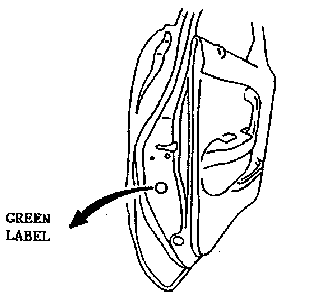
If the driver's side door has a green label, this vehicle is
not a subject vehicle for recall. This vehicle was inspected or
repaired by MMA.
Parts Information
| Part Number |
Description |
| 9999 95 042A 91 |
Recall Label |
| NAY3 43 780 |
ABS Hydraulic Unit |
NOTE:
Recall Labels will be shipped to you without charge for your
initial use. Additional labels can be ordered free of charge from
Helm (800)782-4356.
Repair Procedure
- Step 1 - Inspection
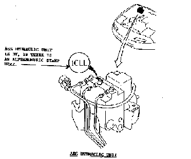
- Verify subject vehicle VIN number to check if the
vehicle falls within the recall VIN range.
- If the ABS Hydraulic unit has an alphanumeric
stamp, such as "1CLL" in the casting at
the indicated area, that ABS Hydraulic unit is
OK. Please proceed to step 5.
- Step 2 - Hydraulic Unit Replacement
- Caution: Brake fluid damages painted surfaces. If you
get brake fluid on your hands and clothing, remove it
before you transfer it to a painted surface. Perform all
repairs with the ignition key in the "OFF"
position.
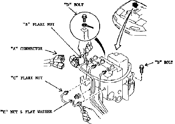
A. Removal
- Place a protective cover on the right front .
- Place a shop towel on the bottom and side of the
Hydraulic Unit Assembly. A drain pan placed under
the hydraulic unit will prevent floor .
- Disconnect the 2 electrical connectors in
portion .
- Loosen 3 flare nuts in portion B with suitable
l0mm flare nut wrench. Loosen 2 flare nuts in
portion C with suitable l0mm flare nut wrench.
Note: You can use the SST(P/N: 490259 770B)
as a suitable 10 mm flare nut wrench.
- Remove I nut and washer in portion .
- Remove 2 bolts in portion .
- Remove the Hydraulic Unit Assembly.
B.Installation
- Note: Replacement unit is filled with brake fluid to
aid air bleeding procedure. Remove plastic plugs by
unscrewing them. Use caution not to spill the fluid.
- Place the ABS unit into position, fasten the
ground cable to the outer mounting point, install
the outer rear mounting bolt and front nut and
washer. See portion D .
- Tighten 1 nut and washer in portion E and 2
bolts in portion D..
- Tighten 2 flare nuts in portion C to the
Hydraulic Unit Assembly.
- Tighten 3 flare nuts in portion B to the
Hydraulic Unit Assembly.
- Reconnect the connector A completely (until a
click sound is heard.) .
- Flush the area around the ABS unit to prevent
drips occurring after the customer receives the
vehicle.
Note: To facilitate installation of the 2
lower brake lines, removal of 2 attaching clamps
for wiring harness is recommended.
- Flare Nut Tightening Torque. ("B" and
"C")
- 13-22Nm 1.3-2.2 m-kg. 10-16 ft.-lb.
- Bolt and Nut Tightening Torque. ("D"
and "E")
- l9~25 Nm 1.9-2.6 m-kg. 14-19 ft.-lb.
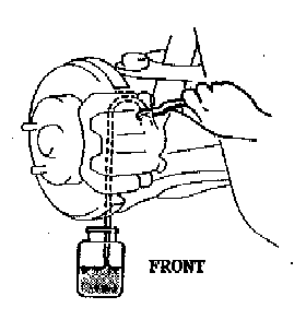
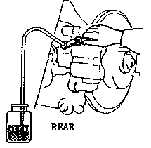
- Step 3 - Air Bleeding (Manual process shown)
| Brake Fluid Type - DOT 3 FMVSSll6
or SAEJ1703
|
- Caution : The fluid in the reservoir must be
maintained at the 3/4 level or higher during air
bleeding.
Do not spill brake fluid onto painted surfaces.
- Notes:
- If utilizing a power bleeder, follow
manufacturers instructions supplied with
the unit.
- This procedure must be performed by a
qualified brake service technician.
- Wheel bleeding sequence left rear, right
rear, left front, right-front.
- Raise the vehicle on a hoist.
- Remove the rubber cap on the bleeder valve and
attach a rubber tube to the bleeder valve with
the SST. (P/N: 490259 770B)
- Place the other end of the rubber tube in a clear
container and keep the tube end immersed in brake
fluid during air bleeding.
- Pump the brake pedal several times.
- While maintaining the depressed brake pedal,
loosen the bleeder screw to let fluid and air
escape.
- Tightening torque
- Front:5.9-8.8 Nm (60-90 cm-kg, 56-78
in-1b)
- Rear: 6.9-9.8 Nm (70-100 cm-kg, 61-87
in-lb)
- Repeat Steps 4 and 5 at each wheel location until
there are no air bubbles in the fluid.
- Check for correct brake operation.
- Check that there is no fluid leakage. Be sure to
clean away any spilled fluid with rags.
- After bleeding the air, add brake fluid to the
specified level in the reservoir.
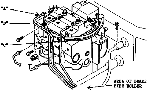
- Step 4 - Inspection after installation
- Note: Be sure that the brake pipe lines are correctly
installed to the hydraulic unit as shown in the
illustration.
- The brake pipe for the front left wheel has a
yellow marking. This pipe should be connected to
the right connector of the ABS unit as shown in
portion A.
- The brake pipe for the front right wheel should
be connected to the center connector of the ABS
unit as shown in portion B.
- The brake pipe for the rear wheels should be
connected to The left connector of the ABS unit
as shown in portion C.
Caution: Be sure that there are no
obstructions with the routing of the brake pipe
lines, and that the brake pipe lines have not
been removed from the pipe holders.
- Check the ABS warning light when the ignition
switch is turned on, the ABS warning light should
come on and 3 seconds after the engine starts,
the ABS warning light should be off.
- Road Test. Be sure the pedal is firm and not
spongy.
- Step 5 - Affixing the Recall Label
-
-
- Affix the Recall label onto the driver's side
door for future confirmation that the Recall
Campaign has been carried out for that vehicle.
Back to Service Bulletins
 Robert T. Evan
Vice president, Customer Support
Mazda Motor of America, Inc."
Robert T. Evan Vice president, Customer Support Mazda Motor of America, Inc."
 MX-5 Miata with ABS

